
|
How to Capture the Simulation Screen Display
|

|
|
Screen capture is always required for users to edit manual guide. There are two ways of capturing the simulation screen display:
A. Capture screen on PC;
B. Use “Screen hard copy” function of EasyBuilder Pro:
A. Capture screen on PC
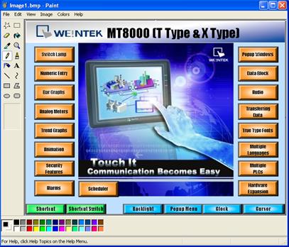
During on-line simulation or off-line simulation, press “Alt+Print Screen” on keyboard to capture the simulation screen. Paste it into an image editing tool and save it.
B. Use “Screen hard copy” function of EasyBuilder Pro
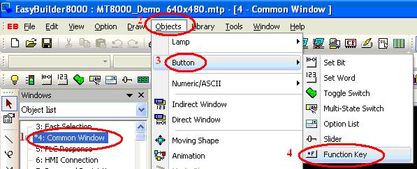
1. Open EasyBuilder Pro project file. Create a function key and check the “Screen hard copy” radio box in the general setting window. Set the printer to “USB disk 1”.
Notice: It is suggested to create the function key object in the “Common Window”, since that the objects in this window can be applied to all other windows;
Click “Object / Button / Function Key”:
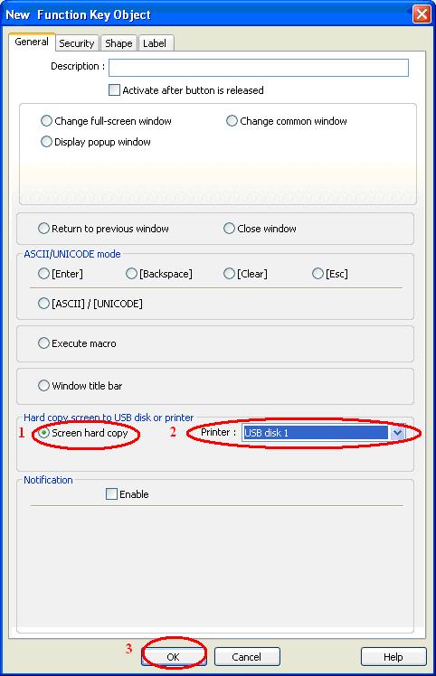
2. In the popup window, check the “Screen hard copy” radio box under the “General” tab. Set the printer to “USB disk 1”. Click “OK” to finish
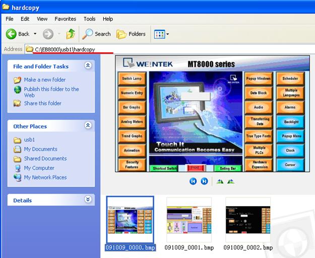
3. Start off-line simulation. Click the print button that is created in the previous step to capture the simulation screen and save it as an image file under the path “\usb1\hardcopy”.
The image is saved in the following path C:\EasyBuilder Pro\usb1\hardcopy:
|
|
|
|
How to backup a project
|
|
|
An EasyBuilder Pro project contains the source project file (*.mtp), and a number of library files (*.flb, *.blb, *.plb, *.slb, *.snd, *.lbl, and *.glb). These can be individually copied to another location for archiving, or to select theCompress/Uncompress option from EasyBuilder Pro's Tools menu.
Step 1.
Click Compress/Uncompress from Tools menu.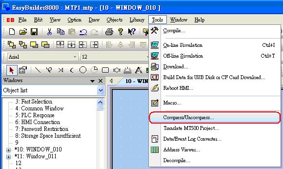
Step 2.
The following dialog is displayed. Click “Browse” to select source project for archiving.
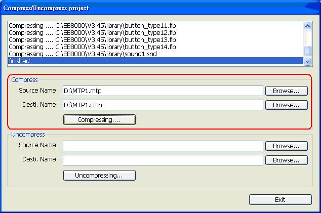
All of the files associated with the project are compressed into a file, with a name of the form *.cmp. The compressed CMP file can be properly archived when this step is successfully completed. |
|
|
|
How to download startup screen?
|
|
|
After a custom BMP image is downloaded to the HMI for use as the startup screen, the HMI will reboot and display this image before accessing the project.
For eMT, iP, iE, XE, mTV Series HMI
Below are two methods to download the startup screen.
Method 1: Utility Manager
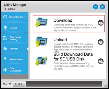
Step 1. Open Utility Manager.
Step 2. Click [Download].
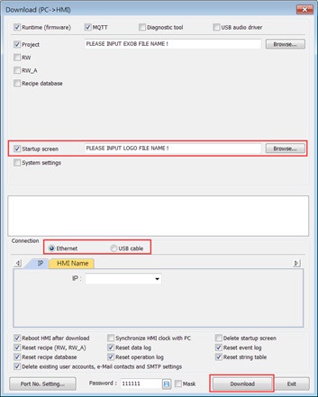
Step 3. Select [Startup screen] and browse for a BMP image file that matches the size of the HMI screen. For example, for eMT3070, use an image size of 800*480 or smaller.
Step 4. Choose to download via Ethernet, set the correct HMI IP address, or use a USB download cable.
Step 5. Click [Download], and the HMI will display the startup screen during reboot.
Method 2: EasyBuilder Pro
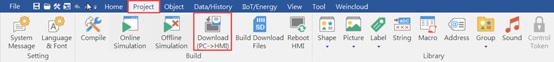
Step 1. Open EasyBuilder Pro and click [Project] » [Download (PC -> HMI)].
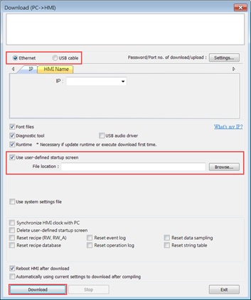
Step 2. Choose to download via Ethernet, set the correct HMI IP address, or use a USB download cable.
Step 3. Select [User user-defined startup screen] and browse for a BMP image file that matches the size of the HMI screen. For example, for eMT3070, use an image size of 800*480 or smaller.
Step 4. Click [Download], and the HMI will display the startup screen during reboot.
For cMT, cMT X Series HMI
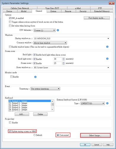
Step 1. Open EasyBuilder Pro and click [Home] » [System Parameters].

Step 2. In the [General] tab, select [Update startup screen on HMI] » [Customized] » [Select Image], and choose a BMP image file that matches the size of the HMI screen.
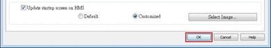
Step 3. After selecting an image as the startup screen, click [OK] in System Parameter Settings to add this image to the project file. The startup screen will be downloaded to the HMI along with the project file.
|
|
|
EasyBuilder Pro - Alignment
|
|
|
In EasyBuilder Pro, there are two different ways to align the text on the object, one is to click the icons on the toolbar and the other is to set on object setting dialog.
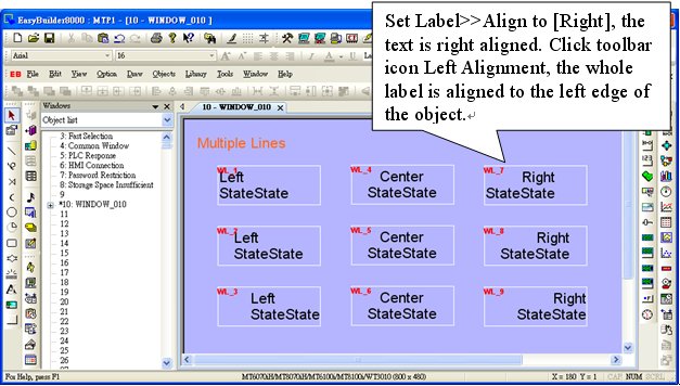
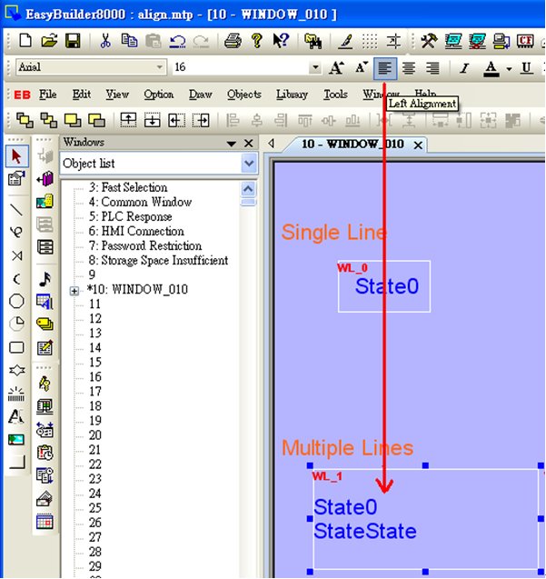
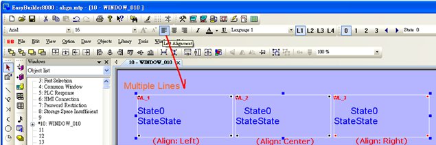
- By clicking the icons on toolbar (Left Alignment | Center Alignment | Right Alignment), the text, no matter single-lined or multi-lined, will be seen as one single label and will align to the outline of the object.
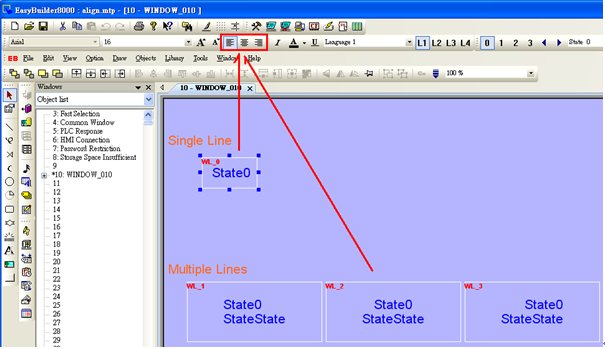
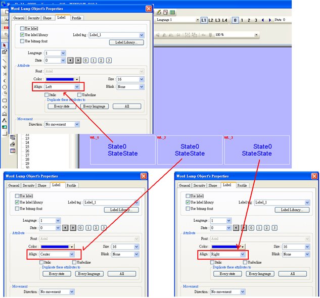
- By setting Label>>Align on object setting dialog, the multiple lines of the text will align in the way set. This is a line by line alignment.
- The line by line alignment of the multi-lined text can be done using Label>>Attribute selection on object setting dialog.
- If an object is set to [Left] for [Align], when clicking [Left Alignment] on toolbar, the multi-lined text will be aligned along the left edge of the object.
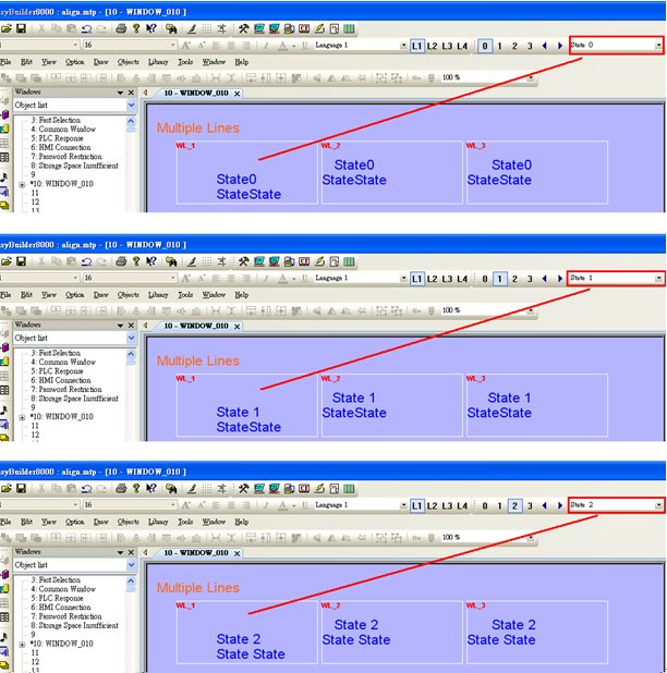
- If object text is set with multiple states, tick [Tracking], in this way when moving text in one state, the texts of other states will also be moved in the same way.
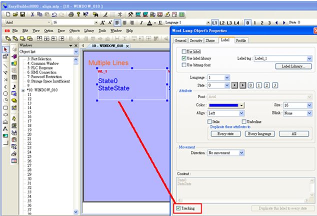
- Move object text in state 0; check the other states to see if the texts in those states all move the same way as in state 0. If [Tracking] is not selected, only text in one state will be moved.
|
|
|
How to download project by Ethernet
|
|
|
This FAQ explains how to download project file to HMI via Ethernet.
Applicable models: eMT Series, iE Series, XE Series, mTV Series, i Series
Non-applicable models: cMT Series
HMI Settings
Step 1. Click on the  Arrow icon in the lower-right corner of the screen. Arrow icon in the lower-right corner of the screen.
Step 2. The following four icons will be shown, click the first Gear icon.

Step 3. Enter password (default is 111111). If the password is correct, the System Settings window opens.
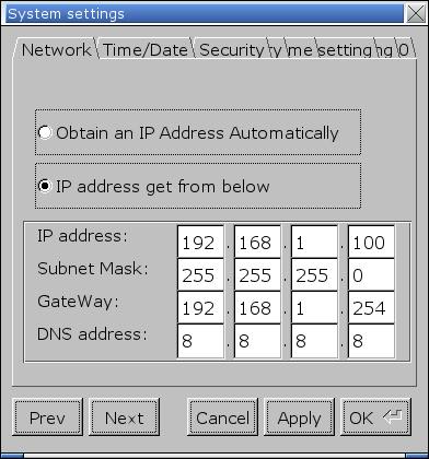
Step 4. In Network tab, set the IP address. Select [Obtain IP Address Automatically] to get IP settings automatically, or select [IP address get from below] to specify an IP address. After setting click [Apply] or [OK] to finish.
Step 5. In Security tab, set the project upload/download password. Click [Download Password] and enter the password. By default, the download password is 111111.
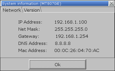
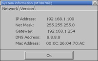
Step 6. When finish setting and leave System Settings window, click the Arrow icon again. Select the Notepad icon to find the IP address of the HMI.

PC Settings
Step 1. Click the Start button and then click [Control Panel]. Under [Network and Sharing Center] click [View network status and tasks]. Click [Local Area Connection] » [Properties], and then double click [Internet Protocol Version 4 (TCP/IPv4)] to open the settings page.
Step 2. Set the network on PC to the same settings as HMI. For example, as shown in the preceding figure, the HMI IP is 192.168.1.100, so the IP of the PC should be 192.168.1.xxx, where x stands for any number.
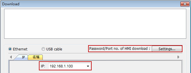
Step 3. To download the project, set the IP and download password in Download window.
Download PDF
|
|
|
Notes on USB Cable
|
|
|
The following are some important points relevant to USB cable:
HI-SPEED USB Revision 2.0 SHIELDED 24AWG
1. The PC must support USB 2.0 or USB 3.0.
2. Use a double shielding USB cable: Foil + Braid Shield.

3. The length of the cable should be limited to less than 1.8 meters.
4. If a desktop is used, the USB cable must be plugged into the back panel instead of the front. If a laptop is used, please remove the external power supply.
5. When downloading a project through USB cable, please remove all the other devices that are connected to HMI.
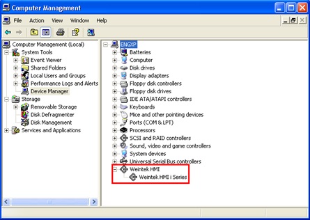
6. If download fails, the possible cause can be the incompatible USB driver on PC. Go to Computer Management » Device Manager to check if the correct USB driver is installed. If not, please go to the installation folder of EasyBuilder and find the usbdriver folder, to manually update the driver.
|
|
|
How to use the VNC server?
|
|
|
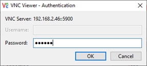
The VNC server is a standard feature on the HMI, allowing users to monitor HMI screen through a VNC client program.
Step 1. Enable the VNC server on the HMI. A single-connection allows only one VNC client connection at a time, while there is no such restriction for multi-connection.
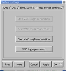 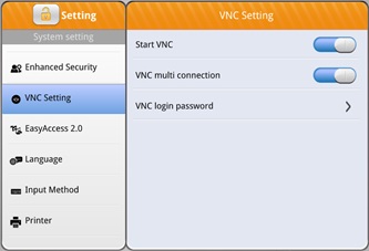
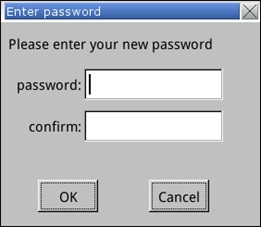
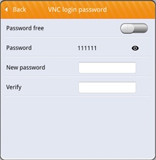
Step 2. The default VNC login password is 111111, which can be changed on the VNC server.
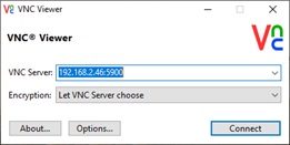
Step 3. Use a third-party VNC client program, enter the HMI's IP and Port (5900), then proceed by entering the login password to access the HMI screen.
|
|
|
TCP Port List
|
|
|
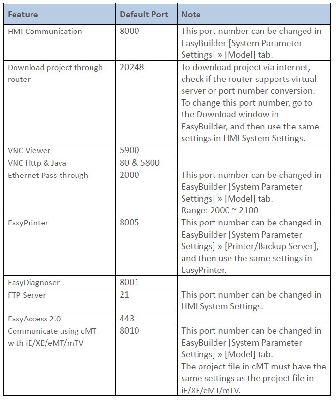
This FAQ introduces the TCP ports used for certain HMI features.
Download PDF
|
|
|
How to do floating point calculations with integers?
|
|
|
To gain a result with decimal place when dividing integers, please convert the integer to float first.
Please see the following Macro. D8=5 is the integer value gained from PLC.
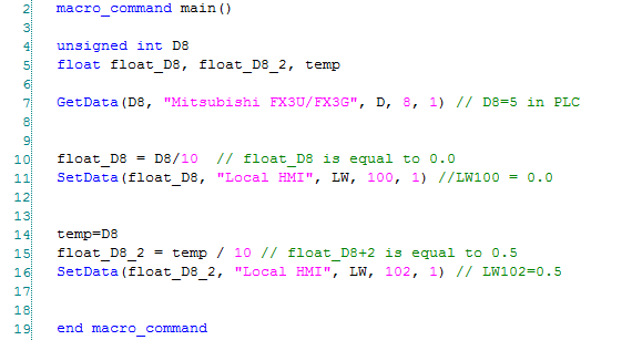
Line 10: Since D8 is an integer, D8/10 is performed as an integer operation and the result is 0. The result is then written to a float variable, float_D8, therefore float_D8 is 0.0.
Line 15: Since temp is a float, temp/10 is performed as a float operation and the result is 0.5.
Download PDF
|
|
|
How to correctly display the project content in different DPI settings?
|
|
|
The computer display resolution is getting higher and higher, in order to display the text clearer, changing the DPI is a choice. However, this also influences the EasyBuilder project display. Incorrect display can happen due to the difference in DPI settings from one computer to another. To avoid this, please follow the steps to adjust the DPI setting.
Checking the current size of text
Step 1. Click the right mouse button on the desktop and select [screen resolution] » [Resolution]。
Adjusting the DPI of EasyBuilder project
Step 1. Launch EasyBuilder Pro, select [Tools] » [Text DPI Setting].
Step 2. Choose [Select the previous PC’s text DPI setting], adjust the DPI to the same setting as the previous computer used to create this project. The text will be correctly displayed. Click [OK]; the system will generate a BAK file for future reference.
Step 3. The DPI setting will be stored in the system. Next time when opening this project file, the previous PC’s DPI setting will be used.
Download PDF
|
|
|
How to Connect Multiple Devices via One Serial Port?
|
|
|
To connect multiple devices via a single serial port, certain station number can be specified when configuring the serial port in System Parameter Settings » Device List. This FAQ explains the syntax of the variables that can be used when setting the station number for the read/write address of an object.
When setting the read/write address of an object, use the syntax “SN#address”. As shown in the following figure, 2#1 indicates station number 2, address 3x1.
Or, use syntax “VARn#address”. The valid VARn range is from LW-10000 (VAR0) to LW-10015 (VAR15). As shown in the following figure, VAR5#2 indicates that the station number is determined by the value in LW-10005 (VAR5).
|
|
|
How to Backup Data to Server and Update in Excel?
|
|
|
To update data backup in remote backup server to an Excel file, please follow the steps below.
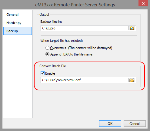
For details of Backup object settings in EasyPrinter and EasyBuilder, see Chapter 26 EasyPrinter and Chapter 13.24 Backup.
Step 1. In EasyPrinter, under Convert Batch File select [Enable] check box. This enables converting file backup into Excel file.
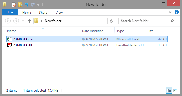
Step 2. When backup file to server, a .csv file is generated.
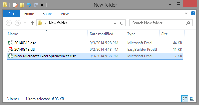
Step 3. Create a new Excel file.
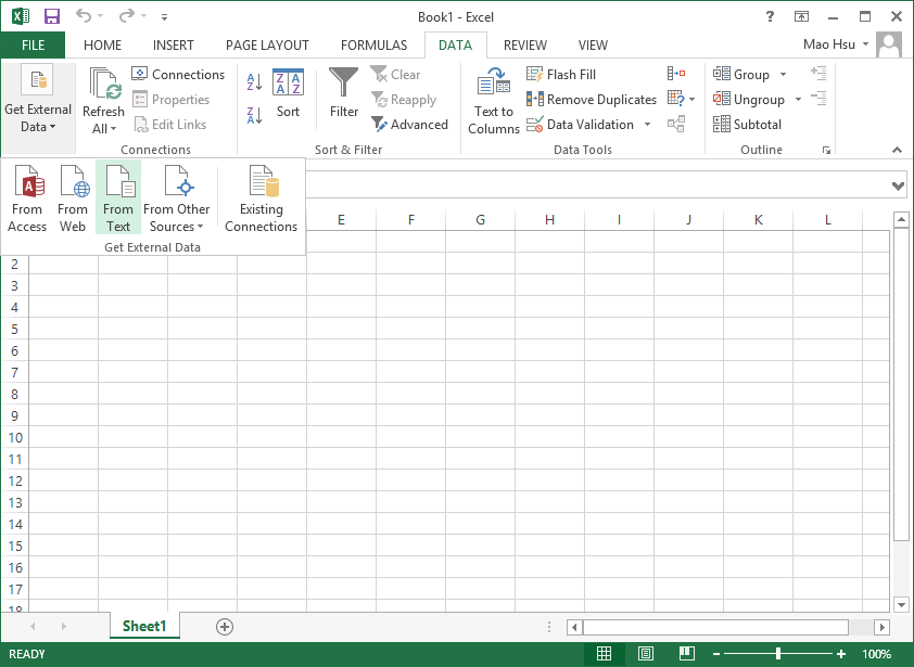
Step 4. Open the created Excel file, import the content in the .csv file by clicking [Data] \ [Get External Data] \ [From Text].
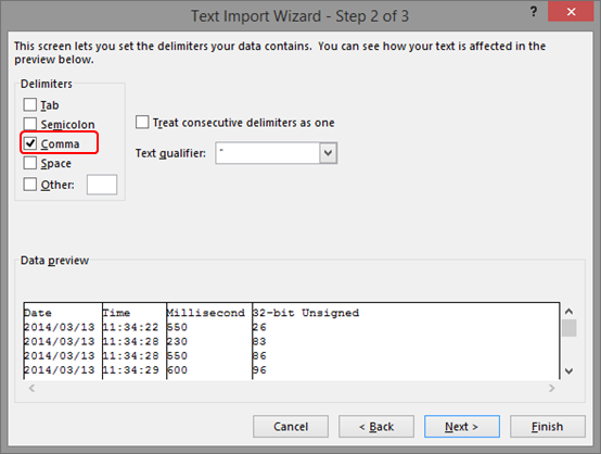
Step 5. During import, select [Comma] to be the delimiters.
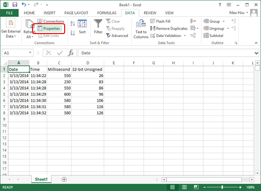
Step 6. When finished, the content in the .csv file can be viewed in Excel. Click [Data] and set [Properties].
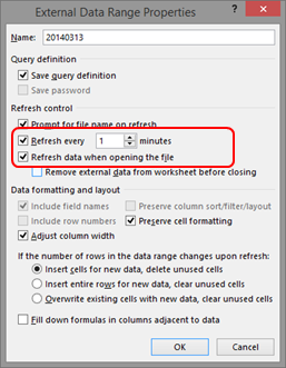
Step 7. Set the time interval to refresh the Excel file, and select [Refresh data when opening the file].
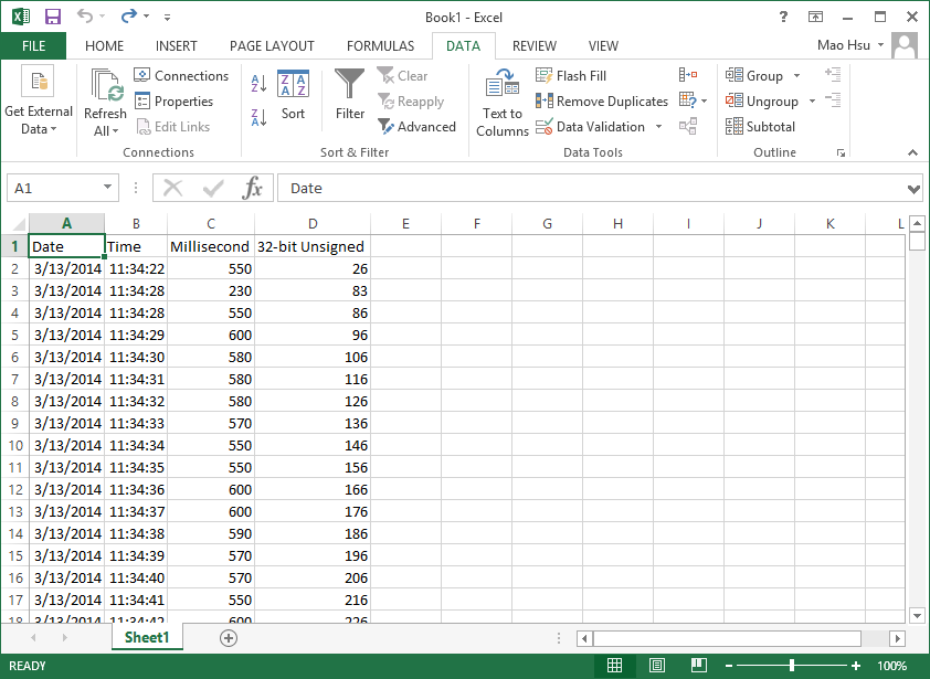
Step 8. In this way, when backup file to server, the generated .csv file is automatically imported to Excel, therefore users can always view the updated data when opening the Excel file.
Download PDF
|
|
|
How to set the HMI IP address on the HMI?
|
|
|
For cMT / cMT X Series:
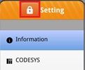
Step 1. Tap the round button in the upper-left corner (default) of the HMI screen.

Step 2. The [System Setting] window will appear. Tap the lock icon.
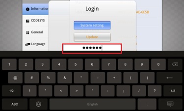
Step 3. Enter the password (default is 111111) to access the system settings.
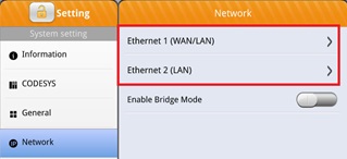
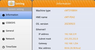
Step 4. In the Network page, select the desired network interface (Ethernet 1 / Ethernet 2).
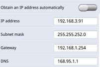
Step 5. Choose either to obtain an IP address automatically or manually set it. Tap [OK] to save the settings.
[Obtain an IP address automatically]=ON: Automatically obtain IP.

[Obtain an IP address automatically]=OFF: Manually set IP.
Step 6. After exiting [Network], tap [Information] to view the current HMI IP settings under Ethernet 1.
For eMT, iE, XE, mTV, iP Series, etc.:
Step 1. Tap the arrow icon  in the lower-right corner of the HMI screen. in the lower-right corner of the HMI screen.
Step 2. Four icons will appear. Tap the first gear icon.

Step 3. Enter the password (default is 111111) to access the system settings.

In the Network tab, select either:
[Obtain an IP Address Automatically]: Automatically obtain IP.
[IP address get from below]: Manually set IP.
After configuring, tap [Apply] or [OK] to save the settings.
Step 4. Exit the system settings window, then tap the arrow icon again and select the notepad icon to view the current HMI IP settings in the Network tab.

|
|
|
How to display project in portrait mode on HMI?
|
|
|
If the project file is designed in portrait mode, follow these steps to correctly display it on the HMI.
Step 1. For eMT / iE / XE /iP /mTV series HMI, go to [System settings] » [OS setting] and adjust the rotation angle to 90 or 270 degrees.
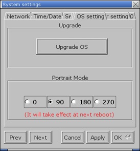
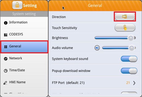
For cMT / cMT X Series HMI, go to [System setting] » [General] » [Direction] and adjust the display mode.
Step 2. Open EasyBuilder Pro, click on [File] » [New], and set the orientation to [Portrait].
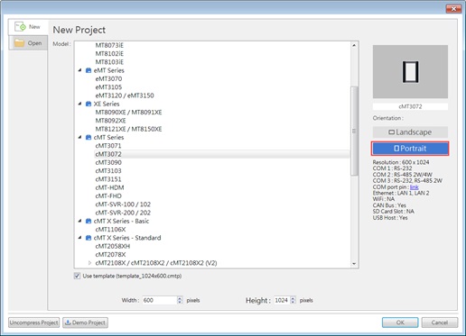
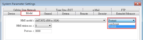
If [Landscape] was selected when creating this project, change it to [Portrait] in the [System Parameter Settings] » [Model] tab.
|
|
|
Why can’t I open cMT Viewer or the screen is blank after opening cMT Viewer?
|
|
|
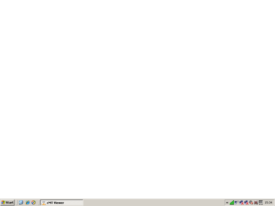
When using an older computer to open cMT Viewer, sometimes the system may show error message or the screen may be blank. This document shows how to solve this issue.
The cMT Viewer application requires a 3D graphic API, OpenGL (Open Graphics Library) newer than version 2.1. If you use an older PC or laptop that runs the OS like Windows XP or Windows Vista, the driver of the graphic chips may be outdated, and doesn’t support newer version’s OpenGL. Please download the latest driver of the graphic chip from the supplier.
|
|
|
How to change the HMI model in the project?
|
|
|
Adapting the project model to meet diverse customer needs is a common practice. By streamlining this process, significant reductions in both time and costs associated with unnecessary edits can be achieved. Below is an example demonstrating a smooth transition from MT8103iE (1024 x 600) to cMT3108XP (1280 x 800).
Step 1. Open EasyBuilder Pro with the file for MT8103iE.
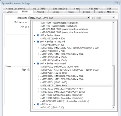
Step 2. Go to [Home] » [System Parameters] » [Model] » [HMI model], then choose cMT3108XP (1280 x 800).
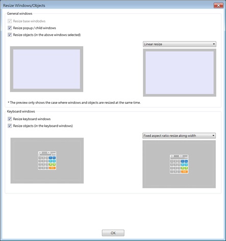
Step 3. After pressing OK, select window and object adjustments in the "Resize Windows/Objects" dialog box, which appears due to the varying resolutions of HMI models. Then, recompile and download the project to the new model.
Step 4. After pressing OK, if converting from the MT Series to the cMT/cMT X Series, an additional Project Migration Report will appear. This report informs about the automatic changes made by EasyBuilder Pro.
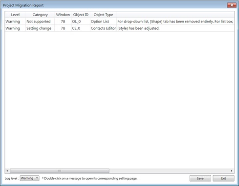
Note: The files from the cMT/cMT X Series cannot be converted to MT Series files.
|
|
|
Port Number 8000 Occupied
|
|
|
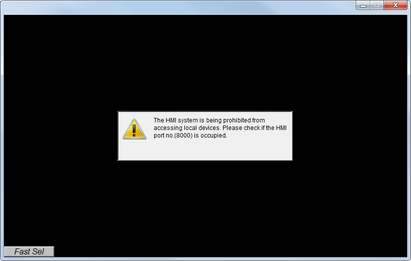
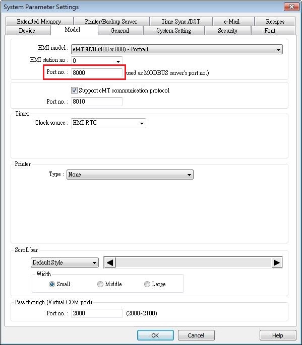
When running project simulation on PC, if the following message is displayed, the possible reason is that the communication port number 8000 is occupied by other application, and therefore the simulation cannot be carried out. This FAQ explains how to check and change port number to solve this problem.
Step 1. Please use TCPView to check if port no. 8000 is occupied. You can download TCPView using the following link:
https://technet.microsoft.com/en-us/sysinternals/tcpview.aspx
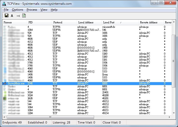
Step 2. If port no. 8000 is occupied, you can change the port number in EasyBuilder System Parameter Settings » Model tab.
Download PDF
|
|
|
How to download project and history data using USB disk or SD card
|
|
|
Utility Manager can build download data and save the data in USB disk or SD card. The data such as project file, recipe data, and history data can be downloaded to HMI using the USB disk or SD card, as a way to update HMI data.
Please note that the described methods are not applicable for cMT Series.
In this document, “USB/SD” refers to USB drive or SD card.
[Build Download Data for SD/USB Disk]
In Utility Manager click [Publish] » [Build Download Data for SD/USB Disk] to create downloadable data including project file, recipe data, or history data…etc. into USB/SD.
Step 1. Launch Utility Manager and click [Publish] » [Build Download Data for SD/USB Disk].
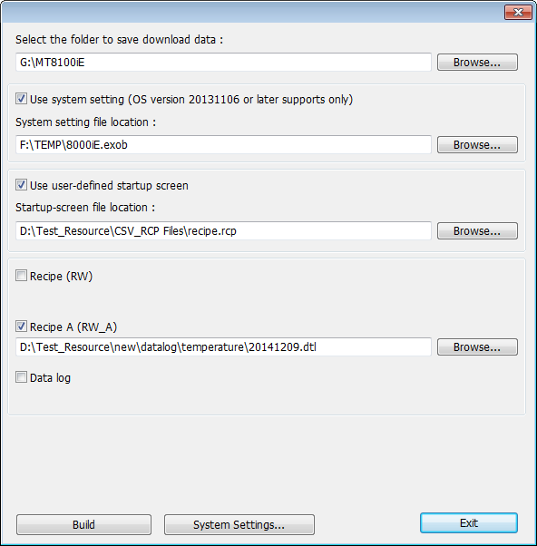
Step 2. Specify the directory of the USB disk or SD card, and the directory of data files, and then click [Build]. For ease of file management, it is recommended that a dedicated folder be created in the USB/SD. You can use a folder name that’s easy to identify, for example, the HMI name or model name.
As shown in the following figure, the folder to save download data is:
G:\MT8100iE
Step 3. If the data is successfully built, a notification message ‘creating successful!’ will show.
[Download to HMI]
Step 4. Insert USB disk or SD card into HMI, the following window will be displayed.
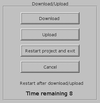
Step 5. Hit [Download], enter HMI download password, select [Download project files] or [Download history files], and then hit [OK]
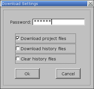
Note: History file includes recipe data (RW, RW_A), and data sampling.
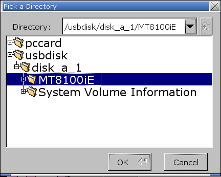
Step 6. Select the directory that has the download file and then hit [OK]. Choose the same directory whether downloading only the project file, only the history data, or both. As shown in the following figure, select the MT8100iE folder created in step 2.
Step 7. During download, the message: “Download Project Files…” or “Download History Files…” is displayed.

Step 8. After download, HMI program will start again.
Download PDF
|
|
|
How to reset HMI to default?
|
|
|
When you need to clear all items and data, restore to factory settings, or if you have forgotten the system settings password and need to reset it to the default value, follow the steps below.
Please note that resetting to factory settings will restore all passwords to the default value "111111" and will clear all projects and historical data. Additionally, system setting parameters will be restored to default values, including network and VNC server settings.
For cMT / cMT X Series
a. Using the Reset Options in system settings:
For OS versions before 20231201:
Step 1. Enter the system settings password. If you have forgotten the password, enter "default111111" in the password field and proceed to step 3 directly.
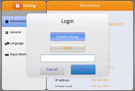
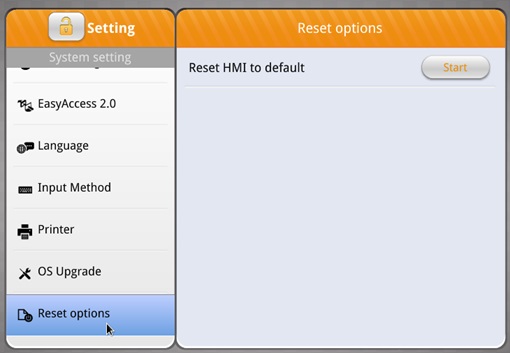
Step 2. Find Reset Options / Reset HMI to Default and click [Start].
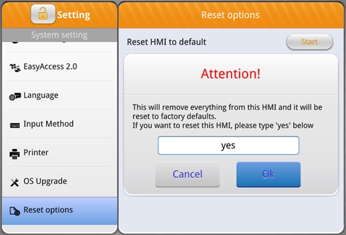
Step 3. Follow the on-screen prompt to enter "yes" and click [OK], the system will begin the reset process.
For OS versions after 20231201:
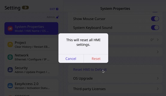
Step 1. Find System Properties / Reset HMI to Default option.
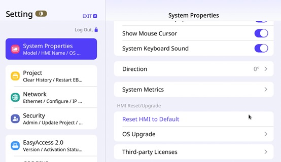
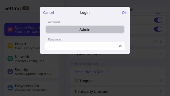
Step 2. Enter the system settings password. If you have forgotten the password, enter "default111111" in the password field and proceed.
Step 3. Tap [Reset], the system will begin the reset process.
b. If your HMI supports DIP switches, you can use them for reset:
Step 1. Set DIP SW1 to ON position.
Step 2. Power on your HMI again.
Step 3. After booting, follow the on-screen prompts to perform touch calibration.
Step 4. Once calibration is completed, follow the on-screen prompts to restore to factory settings.
For non-cMT / cMT X Series
a. Enable the Reset HMI to Default option in system settings:
Step 1. Enter the system settings password.
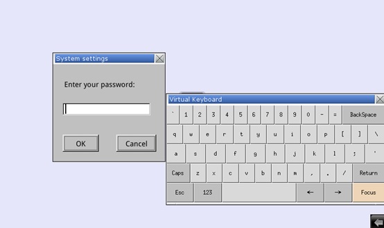
Step 2. In the Misc 2 tab, select “Enable [Reset HMI to default] button in calibration mode” and tap [OK] to save the settings.
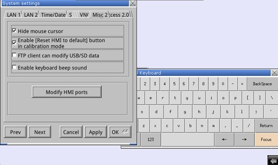
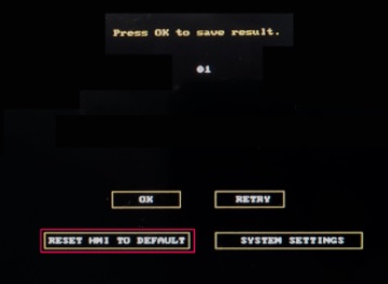
Step 3. Power on the HMI again and long press the screen to enter touch calibration mode. After touch calibration is completed, tap [RESET HMI TO DEFAULT] and follow the on-screen prompts to restore to factory settings.
b. Enable the Reset HMI to Default option via EasyWatch:
Step 1. Connect EasyWatch to the HMI, set LB-12364 to True to display [RESET HMI TO DEFAULT] in touch calibration mode. After setting up, follow the steps in the previous section to reset the system.

c. If your HMI supports DIP switches, you can use them for reset:
Step 1. Set DIP SW1 to ON position.
Step 2. Power on your HMI again.
Step 3. After booting, follow the on-screen prompts to perform touch calibration.
Step 4. Once calibration is completed, follow the on-screen prompts to restore to factory settings.
|
|
|
How to use the fonts installed on PC in EasyBuilder Pro?
|
|
|
When using Windows® 10 64-bit to run EasyBuilder Pro, certain fonts installed on PC may not be found in EasyBuilder Pro. The possible reason is that the font’s installation directory is not detected in EasyBuilder Pro. When encountering this issue, please follow the steps to fix it.
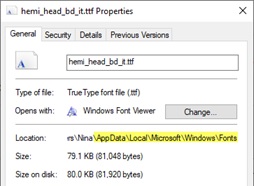
In the following demonstration, the font used is: HemiHeadRg-BoldItalic (hemi head bd it.ttf)
Step 1. Launch the Command Prompt in Windows and enter Regedit. Go to this directory to check whether the font file exist: HKEY_LOCAL_MACHINE\SOFTWARE\MICROSOFT\Windows NT\ CurrentVersion\Fonts
Step 2. If the font file does not exist, open File Manager and enter “C:\Window\Fonts” in the directory field. Or open [Control Panel] » [Fonts] and find the font file.
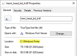
Step 3. Right click on the font file and open its properties to find its installation directory. As shown in the following figure, the font is installed under: %userprofile%\AppData\Local\Microsoft\Windows\Fonts
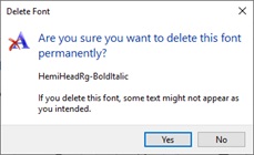
Step 4. Right click on the font file and then select [Delete] to delete it.
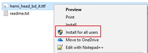
Step 5. Install the font file again, find it, right click, and select [Install for all users].
Step 6. Do step 2 again, open File Manager and check the directory.
Step 7. Restart EasyBuilder Pro, the font can now be used.
|
|
|
How to solve display problems on Weintek software?
|
|
|
If you encounter one of the following problems when using Weintek software on a PC or laptop, please see this solution.
1. The objects appear blurred in EasyBuilder Pro editing screen.
2. Content displayed incorrectly in cMT Viewer.
3. Content displayed incorrectly in EasyLauncher.
4. Content displayed incorrectly in EasyAccess 2.0.
Certain Weintek software requires a newer version of OpenGL (Open Graphics Library), which is an API for rendering 3D vector graphics. If you are using a PC or laptop with an older display driver, the new OpenGL may not be supported.
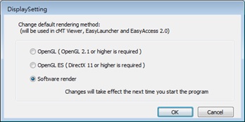
In this case, updating the display driver downloaded from its official website is recommended. If the problem is not solved after updating the driver, please find EasyBuilder Pro folder and run DisplaySetting.exe, and then select “Software render” radio box. The display should appear normal after restarting the Weintek software.
|
|
|
How to replace fuse?
|
|
|
An Internal fuse will prevent damage for overcurrent condition however it isn’t guaranteed. DC voltage sources should provide proper isolation from main AC power and similar hazards. When the fuse is blown, the fuse can be replaced by qualified personnel only. The following steps show how to replace fuse.
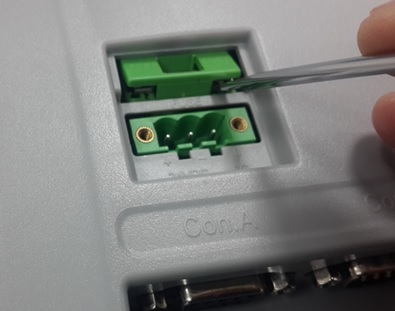
Step 1. Gently open the fuse holder using the tip of a flat-head screwdriver.
Step 2. Remove the blown fuse and replace with a right one for the appliance.
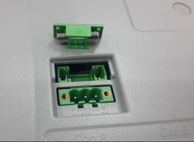
Step 3. Put the fuse holder back to its original place.
|